Contents
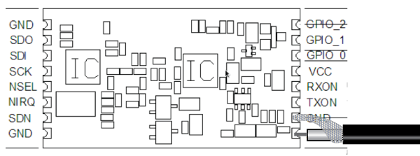
What’s the OrangeRX modules pinout ?

How to improve the range?
Some points to check to improve your range :
Replace the UFL (coax cable) of OrangeRX 1W TX modules
Just do it, the provided cables have very often issues (open or short circuit), sometimes immediately and sometimes after several manipulations.
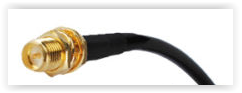
Always replace them by another one, such as this one. One side is a “U.FL” connector, the other side is a SMA connector.
![ori-adaptateur-ufl-sma-20893[1]](http://www.itluxembourg.lu/site/wp-content/uploads/2015/12/ori-adaptateur-ufl-sma-208931.jpg)

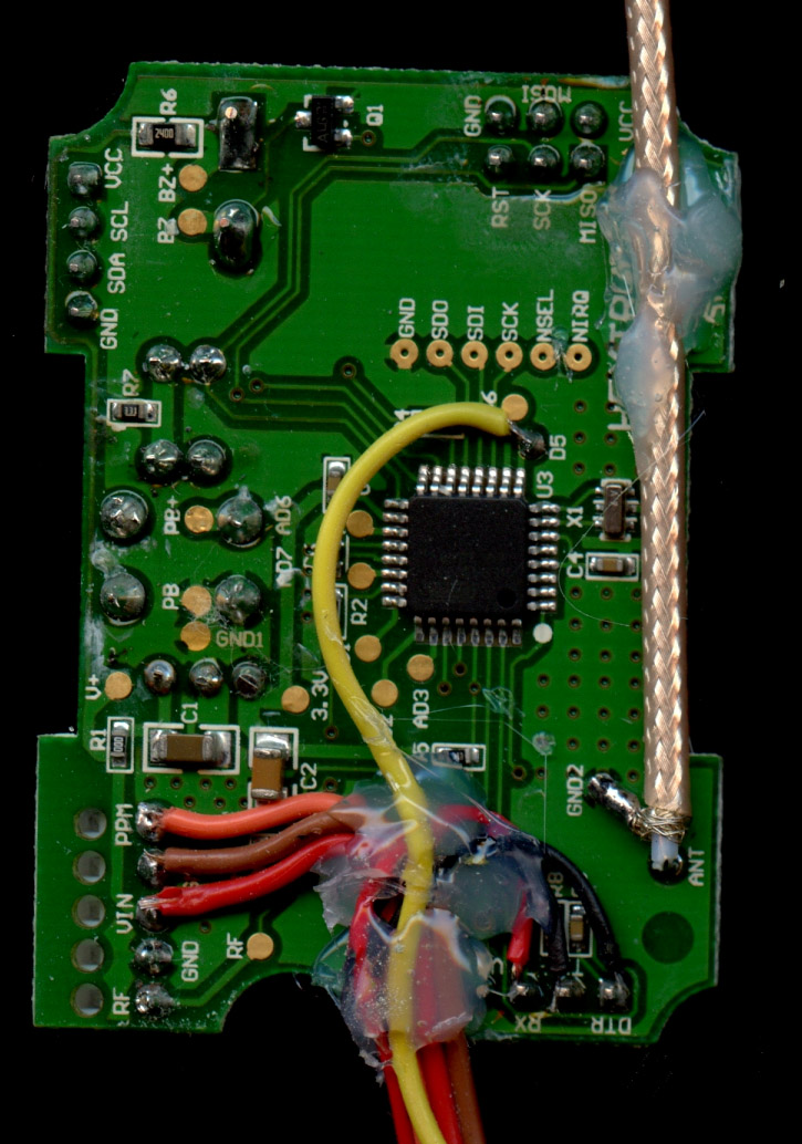
Solder directly to the RFM23BP module pins
Not mandatory, but can avoid unwanted disconnection of the UFL connector.
Like this :
Or like user “salience” from rcgroups.com :
Use a thicker coax cable
Not mandatory, but if you want to place your antenna a bit further (on the car roof for example), consider using a good and thicker 50 ohms coax cable (RG-58), such as this one :

- The stock antennas of OrangeRX modules seem to be 2.4GHz antennas, and will provide a very low range of a few hundred meters.
- Don’t use monopole antennas ! Dipoles are usually sufficient, but some users use other antennas such as yagi, patch, moxon, ground plane, etc. 3)
- Avoid interference sources. Two users who were using bluetooth modules inside or next to the OrangeRX modules have reported lost packets at short range.
- Have a look here for antennas suggestions
How to increase the power ?
The out-of-the-box power of the “1W” OrangeRX is around 400mW. However their RF module can really achieve 1000mW, with a simple modification described on this page.
How to activate the brown-out detector ?
Please see this page for information about the brown-out detector on the OrangeRX modules.
Other issues
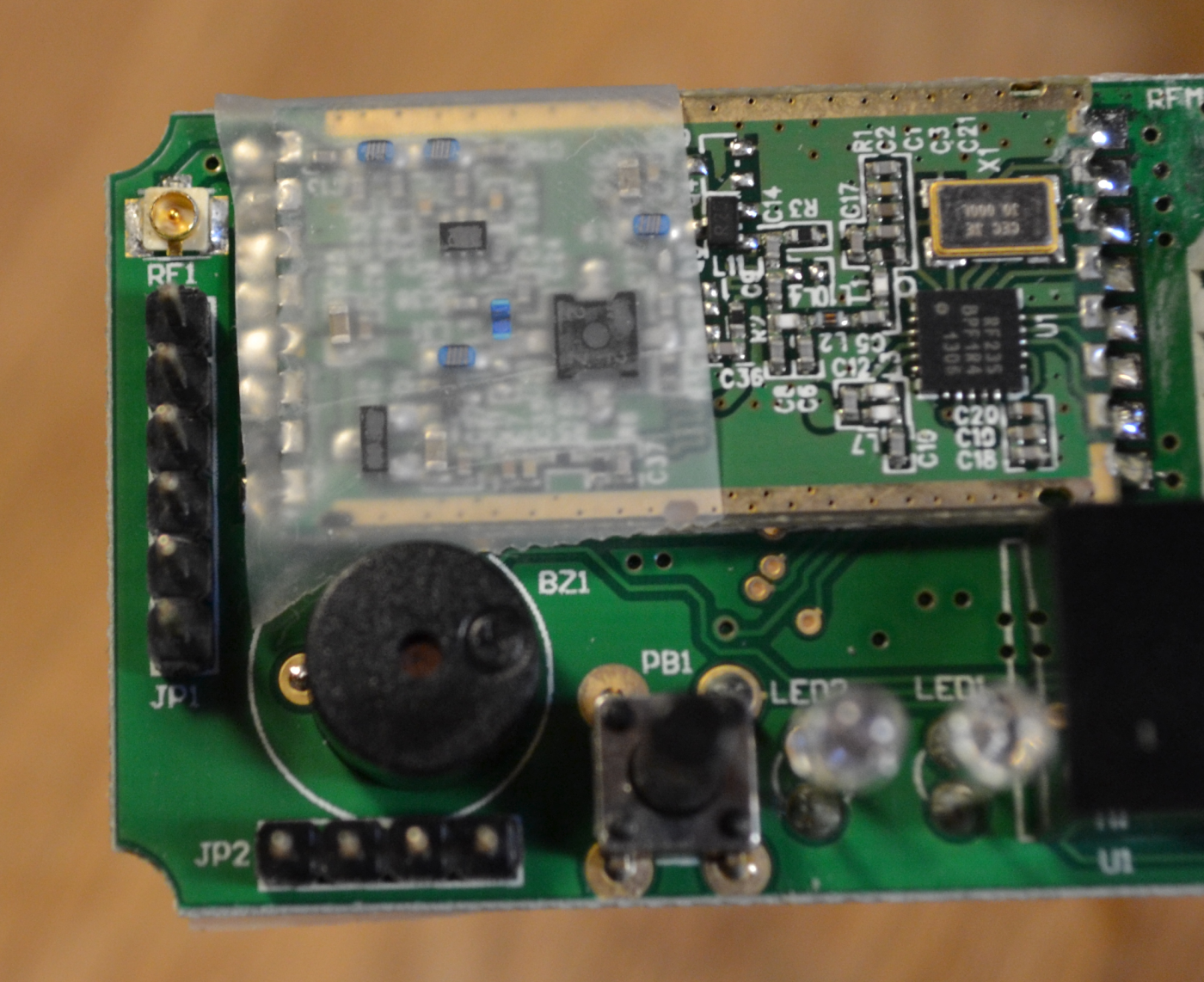
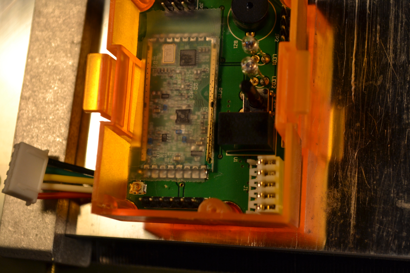
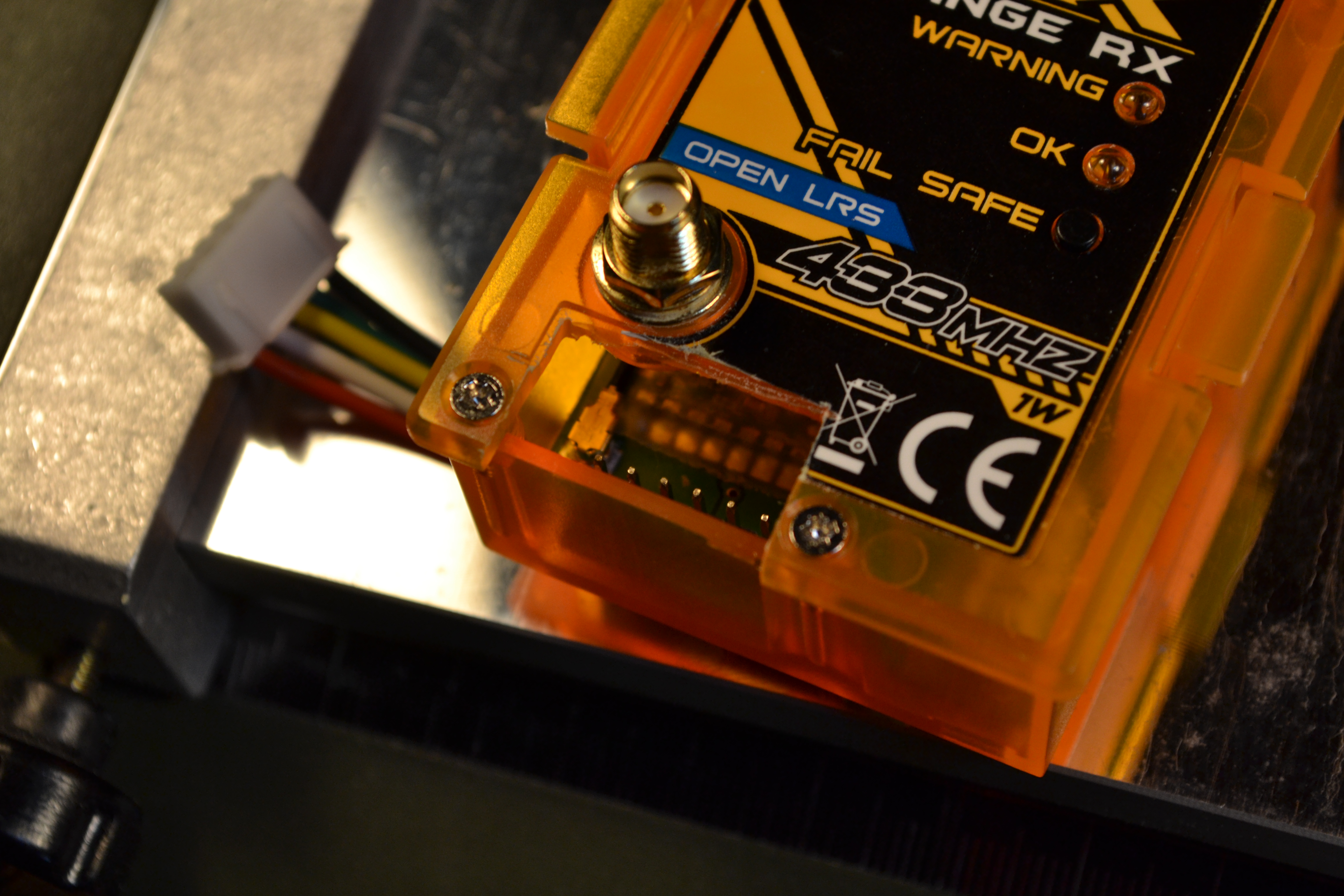
RF connector shorting the RFM module pins
A the connector can rotate, it will easily come in contact with the pins, in particular the first one and that’s problematic : The external part of the RF connector is GND, and when it touches the first pin of the module it shortcuts the antenna. It can damage the module, but usually it will survive a short contact. Maybe this can cause a sudden voltage drop and reset of the atmega too. The photos are from two different brand new modules, first opening. Notice that touching the second pin is not an issue, but touching the first (in the corner of the RFM module) is short circuiting the antenna output. On these two modules it seems that the RF connector is on the second pin, but it’s freely rotating and can touch the first one too.
An option is to use hot glu, another is to cover the RFM23BP pins with tape:

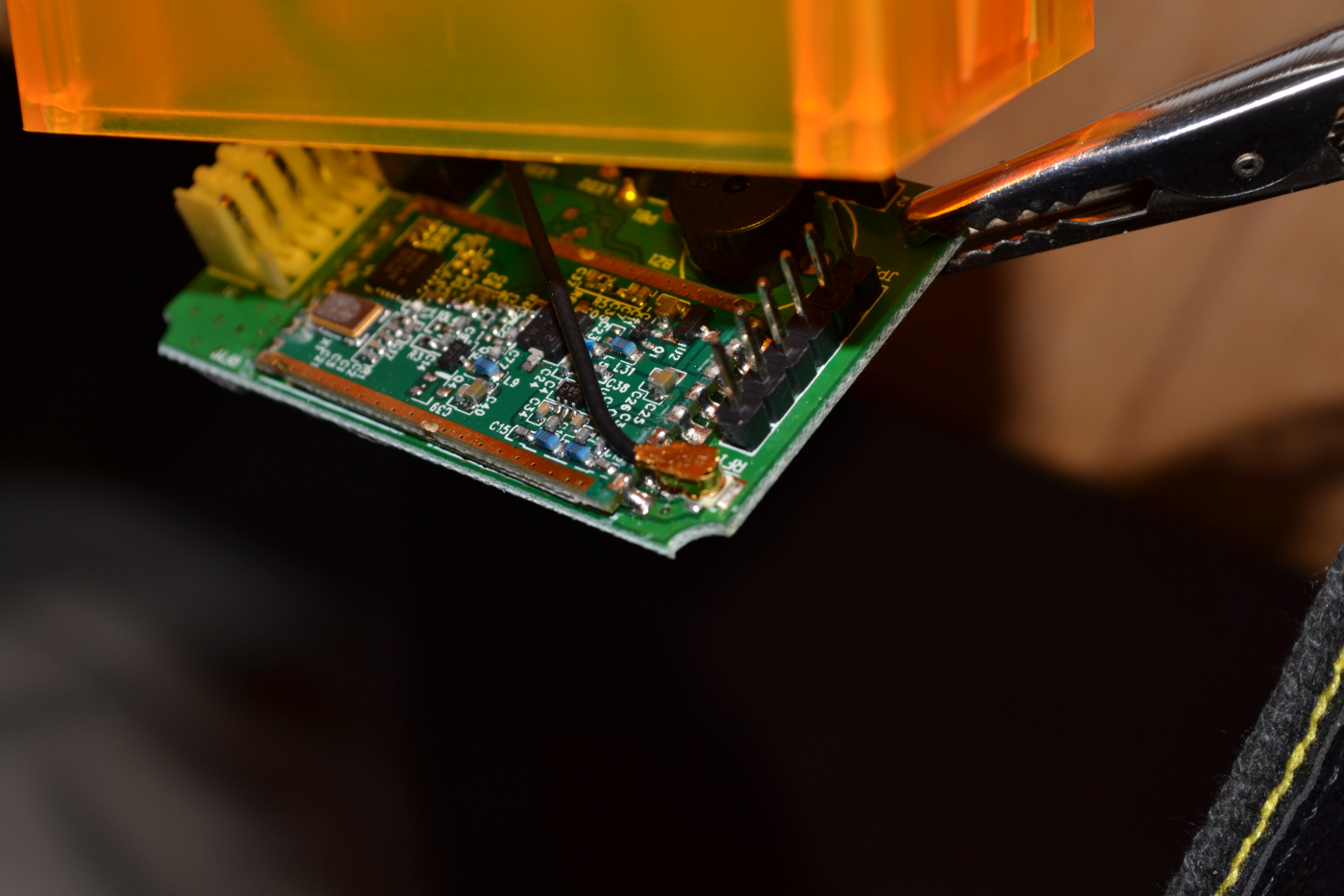
How to access the serial port ?
7The serial port is not accessible by default, and requires to cut a hole into the plastic :
Remark about the pins RX_ON, TX_ON, RX_ANT, TX_ANT
Just for information for people building their own modules, several users are asking if these pins must be connected differently on the 1W and 100mW modules :
The pins RX_ON and TX_ON on the RFM23BP (1W module) are named differently : RX_ANT and TX_ANT on the RFM22B (100mW module), and are reversed.
But their signals are inverted too :
- rfm22b datasheet:
| RX_ANT : Rx Antenna select input pin. When RFM22 is RX state, RX_ANT should be = 1, TX_ANT should be = 0 |
- rfm23bp datasheet:
| Rx ON : select input pin. When RFM23BP is RX state, RX_ON should be = 0, TX_ON should be = 1 |
So in conclusion the wiring must be the same for the 1W and the 100mW modules. It took me several burned modules before understanding this…