
Mod for OrangeRX modules
The out-of-the-box power of the “1W” OrangeRX module is around 400mW. However their RF module can achieve their maximum power of 1000mW, with this simple modification.
The RFM23BP modules have an output power which is dependent on their voltage.
To use the full power, only the RFM module must be powered at 6V, not the atmega or other parts. This is important and will be explained below.
Remark : this is often referred as the “5V mod”, but it’s the “6V mod” because to get the maximum power you need to power it at 6V :

How to proceed
- Cut the PCB track that goes to the VCC pin of the RFM23BP module, then apply 5.5V on the VCC pin of the module.
- Alternatively you can cut the trace that goes from the serial port VCC to the rest of the circuit as on this photo. On the other side of the PCB there’s a trace between the serial 3.3V pin, and the RFM23BP VCC pin, that must stay in place. In this way the RFM23BP can be powered at 5.5V from the easily accessible serial “3.3V” pin, while the rest of the circuits works at 3.3V :

The 5.5V can be provided by a BEC or a separate voltage regulator. For reference, here’s the RFM23BP pinout :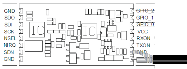 Notice it requires 5.5V to 6V for full power, 5V is already an improvement but is not full power. The chip is designed to work at this power level and doesn’t require a heatsink or any other cooling.
Where to fit the regulator
Rcgroups user Beemond did it and shared some clear photos and explanations in the ULRS thread. An interesting point is that he shows a way to fit the regulator inside the OrangeRX case. Notice that he cuts the track in a different location, but the result is the same : the VCC pin of the RFM23BP module is dissociated from the 3.3V of the rest of the circuit.


Powering at more than 5V ?
A frequent question is why can’t we power the whole OrangeRX module at 5V or 6V by replacing the voltage regulator, as both the ATMEGA328 and RFM23BP can handle up to 6V ?
The issue is that the ATMEGA would then send 5V on the RFM23BP module IO pins, and this is outside its specifications, makes it heat and after a long time destroys it.
The RFM23BP datasheet is unclear on this, and only mentions a max VCC of 6V, but I checked with the manufacturer who confirmed that the voltage on the IO pins must stay at 3.3V, even if the RFM23BP is powered at 6V :
Dear Benoit,
Thanks for your email.
Would you kindly share more information about your company and the application?
How about the forecast?May I know when and where you bought the samples from?
RFM23BP is a module combined with RFM23B and power amplifier.
5V power is for amplifier.
So operated power of chip is 3.3V, and the power of the ports which communicate with MCU is also 3.3V.
It means the voltage of the communication pins is 3.3V.We have many new products with good performance and low price.
Enclosed with the products list for your reference.Best Regards,
Candy Liu
——————————————————————————-
Hope Microelectronics Co., Ltd.2/F Building 3, Pingshan Private Enterprise Science & Technology Park,
Nanshan District, Shenzhen 518057, China
Mailbox: euro@hoperf.com
Websit: http://www.hoperf.com
Choosing a regulator
There are many regulators that will do the job :
Switching regulators
The switching regulators are especially useful if there’s a difference of more than a few volts between input and ouput : in this case a linear regulator would dissipate a lot of power (heat). In addition switching regulator are much more efficient, and some of them can produce a higher output voltage than the input voltage.
To provide an example, this model is well suited for the discussed mod, is adjustable, and can be powered directly from the battery (up to 30V) :

Here’s another module :

Using a S-BEC
Another option is to go for a BEC (or S-BEC for switching battery eliminator circuit). This tends to be larger than the above regulator, but this one was proposed by squidyman and provides a selectable 5V or 6V. So it’s possible to go from 5V to 6V with a switch, for example to extend the range in case of emergency :

Notice that the main S-BEC from the plane or quad can be used as well.
Linear regulator
It’s also possible to use a linear regulator, but the heat will have to be dissipated properly. A model like LM7805 or LM7806 will do the job. Or LM317 which can be adjusted to any voltage with two resistors.
Don’t forget that any regulator has a certain drop-out, which is the minimum voltage difference between input and output for proper operation. It’s usually around 2V, but some regulators are designed for low drop out (LDO) and can work with only 500 mV.
Remark about the switching regulator which is on the OrangeRX module
Here’s a RF measurement of the switching regulator of the 1W module : although it’s possible to find the emissions with a spectrum analyzer at maximum sensitivity, it’s still relatevely low and should not affect RFM.
Here’s centered on 450Mhz, with a span of 50MHz, yellow trace is with ULRS RX active, other trace is when it’s turned off. The main peak is at -118.9 dBm which is below the RFM sensitivity. (Notice that the smallest level for a packet correctly received will have an amplitidue of about -100dBm, or almost 100 time larger than this)

In the lower frequencies, shown here up to 2MHz, we can see
 the switching frequency, but here also it’s really small, and very far from the frequencies that are used by ULRS.
This was measured at maximum sensitivity on the spectrum analyzer, with an antenna against the regulator, through the plastic case. Not sure if this regulator (TSR-1-2433) is much better than another one, but it looks quite clean. Maybe its case contains some protection against RF, like a thin aluminium film.
It’s possible that old switching regulators were creating a lot more interferences because they had much smaller switching frequencies, hence they had to switch larger currents every time, and were creating more interferences.
But this one works very well and creates emissions so low that they can’t affect the RFM module.
Mod for Wolfbox modules
Please refer to this post from rcgroups user AngelKillR.
Be careful that this mod is different from the mod above for OrangeRX modules : in the above mod, the atmega is still powered at 3.3V, so the RFM receives 3.3V signals on its IO pins, which is correct. In the Wolfbox mod, the atmega is powered at 5V and sends 5V signals on the RFM pins, which can damage or destroy it.