Contents
Mission Planner set-up
- Connect your APM via micro USB cable.
- Install Mission Planner from here.
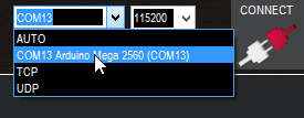
- Select the APM COM port and connect at 115200 bauds for ULRS 1.X, or 57600 for ULRS 2.X
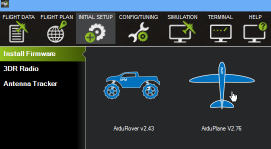
- If not already done, install APM firmware.
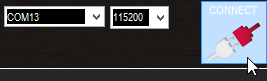
- Connect.
- Go to full parameter list.
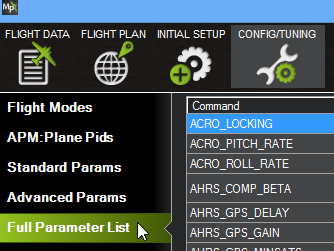
- Click Find

- Search for ‘serial’.
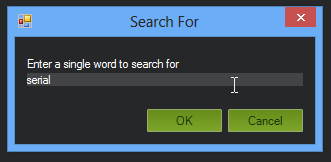
- Change SERIAL1_BAUD to 19 (for 19200 bauds telemetry)
- (Pixhawk users, please check this page)
- Notice that SERIAL1 = UART0, SERIAL2 = UART1, etc
- Write params

- Configure your radio.
- Configure your flight modes (for example use a 3-way switch, and choose manual, FBWA and RTL modes)
Firmware setup
You’ll first install ULRS CC (Ultimate LRS Control Center), which is the ULRS administration tool that allows to :
- download and flash the latest firmware
- configure the parameters such as the channels to use
- check in real time the system status
Installation instructions for ULRS 2.X
Video instructions
Download
Click to download the latest ULRS CC :


Flash firmware to the module
- Connect an OrangeRX module via FTDI cable.
- Select the appropriate COM port.
- The Ultimate LRS Control Center main screen appears.
- Click on the ‘firmware upgrade’ tab.
- Click on the ‘Upgrade firmware’ button.
- The firmware gets uploaded. The HK 1W and 100 mW modules are supported.
- You may have to restart the ULRS CC (bug)
Set parameters
- In ULRS CC, click on ‘connect’
- Click on the ‘modify parameters button’ which is on bottom of the initial status screen. (In previous versions it was a separate tab)
- Double-click on several channels.
- Choose a bindcode.
- Click on ‘Save parameters’
- The popup will close when the parameters are correctly saved.
- Close and restart the application to do the same for the other module. (This will be simplified in the future.)
You’re done !
Congratulations !
Remarks
Disclaimer
I’ll add a complete disclaimer, but basically it’s an experimental system and you have to understand that you use this system at your own risks and under your own responsibility, you’ve got to ensure to comply with all regulations applicable in your country. Don’t do anything forbidden, stupid or dangerous.
In particular, for now it’s possible to select frequencies which are outside of the ISM bands, and the power can be too high for several countries. The OrangeRX modules have a CE certification provided by HobbyKing, but no FCC certification.
Serial speed
Remember that Mission Planner must be connected at 57600 bauds, but APM must be configured for 19200 bauds (SERIAL1 = 19)
WinAVR
WinAVR is required, normally ULRS CC will provide you with a download link if it’s not installed yet. It expects to find it in its default installation folder c:\WinAVR-20100110.
LEDs meaning
On each module, one LED means ‘receiving’ and the other means ‘transmitting’. If everything works fine, all LEDs will blink. The blinking is always at the same rate, which if chosen for good visibility. It doesn’t correspond to packets transmitted, which would be too fast to clearly see the blinking.
The fact that one LED is marked ‘warning’ can be confusing, but having one LED for transmit and one LED for receive allows to debug faster any communication issue. For example if the RX module is broken for any reason, you’ll see only one LED lit on the TX module because it won’t receive any data from the RX module.
FAQ
Have a look at the FAQ, it provides many tips on how to improve your range.
Binding
Notice no binding is needed, it just works out of the box.
RSSI
RSSI is available either as analog signal or as a servo value on any channel.
Please check this page for more information.
Connecting the TX to a computer
If you need more that just the length of your FTDI cable, you can use a long cable to connect the TX to the computer.
You can also consider using Bluetooth as described here.
For example if you have the computer in the car, and want to run a few steps TX in hand to lauch the plane.Two options :
- Connect a 5 meters USB cable to the computer, and have the FTDI adapter near the TX. 5 meter is the maximum as per USB specifications, else you’ll have to insert an USB hub before going another 5 meters.
- or you have the FTDI adapter on the computer, and have a long serial cable. I’ve used 20 meters cable without issues.
About APM and telemetry
IMPORTANT : disconnect the USB cable from APM when using telemetry (when it’s connected, APM will default to 115200 bauds and we’re using the same port for telemetry)
Project origin and history
Know more about the project history here.
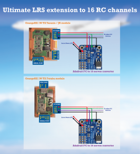
Using 16 channels
ULRS provides a 16 channels PPM signal, but you can also use an external module to have the 16 servo signals : link.

ULRS pinout
Always useful during installation… click to enlarge :