
Contents
Specific preparation of OrangeRX modules
Specific instructions for OrangeRX modules, the other brands or ULRS Mini don’t require this.
Serial port
On OrangeRX modules, drill a hole to access the serial port :
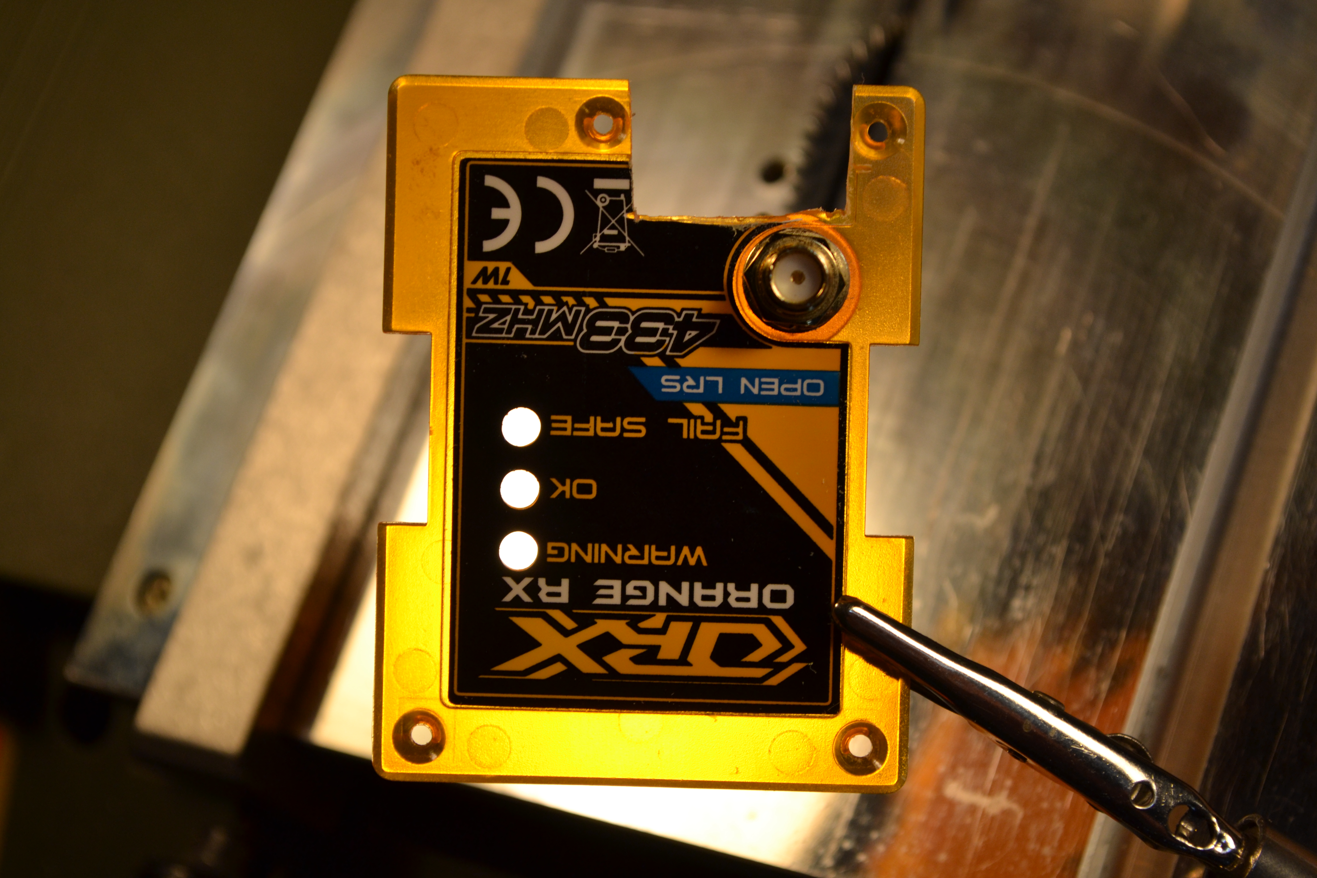
UFL connector
It’s also strongly recommended to replace the UFL (the small coax cable) inside the 1W OrangeRX modules. More details here.
Wiring diagram
Pixhawk users
You’ll find the wiring diagram here.
Other Flight Controllers
ULRS will work with any flight controller that can send 19200 bauds data. Not only mavlink data but any type of serial data.
You’ll find the wiring diagram here.
Now plug and play
- Plug into the transmitter, and connect an USB / FTDI cable:

- For information, here are the TX pins used:


Power supply
1W modules
The below diagrams show the 1W OrangeRX modules powered from the 5V of the BEC or APM power module.
This will work, but for maximum safety power the 1W OrangeRX modules directly from the battery voltage (up to 36V).
100mW modules
The OrangeRX 100mW modules are powered with 5V on any servo port.
Notice that the 100 mW module must not be powered with more than 5Vbecause :
- They only have a linear regulator
- The servos are supposed to work at 5V
The ULRS RX 100 mW can be powered from the APM servo input 1, which is connected to the 4th servo port on the ULRS.
You can alternatively use any other 5V source such as a dedicated UBEC.
Don’t power the 100mW modules via the FTDI port
The only dangerous pin on the 100mW module is the VCC pin of the serial port. It’s recommended to cut it. This pin is directly connected to the VCC pin of the RFM22B, which is a 3.3V device, if by mistake 5V is applied on it the RF module will die immediately. Remember that even the genuine 3.3V FTDI cables from FTDI provide 5V on this pin, that’s why it’s safer to cut it down.
You could apply more voltage on the servo port, because it’s not connected directly (but via a regulator) to the RFM22B. But as you have servos or APM connected on one of the servo ports, don’t apply more than 5V.
Antennas
A list of suitable antennas for ULRS can be found here.
RSSI
More detail about how to obtain the RSSI (Signal Strength Indicator) are here.

Leave a Reply