
Discussion forum on RCgroups is here.
Contents
Introduction
Description
This projects provides drone and FPV flyers with a long range 1 watt bidirectionnal link for remote control and telemetry. Use it to replace your other telemetry or LRS systems by a single system having many advantages :
Performances
With 1W or power, the Ultimate LRS provides full telemetry and RC control for hobby flyers.
Speed
The speed of Ultimate LRS allows to make all mavlink operations in the air. For example connecting, modifying parameters in flight, uploading new waypoints, or any other mavlink command.
It not only support the default Mission Planner telemetry speed, but can handle much more such as 10 refresh per second for the attitude and position, giving completely smooth artificial horizon movements.
A more detailed features comparison with 3DR radios is provided here.
Fast RC link & Mavlink telemetry : 72 packets per second
Complete documentation
The project provides a complete documentation on this site, including clear installation instructions, links to user videos and content, complete spectrum analysis, proposed mods etc.
Active community
A very active user community has grown in this rcgroups forum. Feel free to join the community and propose your ideas and suggestions, or get answers to your questions.
Users have made new 3D printed cases, new antennas designs and videos,click here to see some user provided videos and other ULRS related creations.
Simplicity
The Ultimate LRS is complex inside and simple outside : no technical settings to guess, it’s just plug and play.
Evolutive
Ultimate LRS is a part of a larger project, that includes a complete ground station with a 3D virtual cockpit. This is not the latest status, but gives an idea of the features :
Features
Ultimate LRS Control Center
The ULRS CC is a software running on Windows, which will allow to burn / upgrade the firmware, check the live status, select channels, modify parameters etc.
Its main features are described below :
Status overview
This page shows information about the ULRS, such as :
- Current servo values,
- Global RSSI,
- RSSI per channel
- Background noise per channel
- Chip temperature,
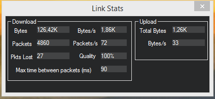
- Connection statistics.
It’s a single-page overview of the system health. It’s possible to simultaneously display this page, Mission Planner andr another ground control software.
The status page shows also the firmware version, failsafe status, and can detect other issues such as uninitialized parameters.
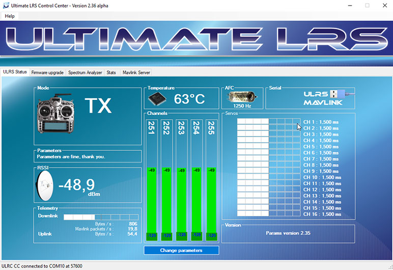
The Status page shows the available COM ports, and will detect automatically ULRS modules connected, if they are RX or TX, and their baudrate (TX = 57600, RX = 19200).
When an ULRS module is detected, its type appears in the selection box on top of the screen, along with the firmware version :
![]()
Select the correct serial port and click on connect.
Real-time spectrum analyzer
It’s on the screenshot above, the “Channels” box : this view shows the currently selected channels, and interesting data about them. The light green bar represents the signal strength for a given channel, and the dark green bar is the noise level for the channels. What’s important is to have a low noise level, and a high signal level. The difference between the two is called the SNR (signal to noise ratio). Currently no other LRS system provide this information, especially not in real time and per channel. The numerical values are expressed in dBm.
To understand why this is useful, think about a sound signal : someone talks to you and there’s almost no background noise, so you hear him or her very well. Then he/she walks progressively farther, while keeping the same voice volume. You hear less and less and at a certain distance you only understand some words. When a car passes near you, you don’t understand anything because it’s too noisy, except if the speaker is really close to you. So what’s important is not the speaker’s perceived volume, but the volume in comparison to the background noise.
It’s the same for the ULRS. Rather than just measuring the perceived volume (Signal Strength), we will also measure the background noise. The difference between the perceived volume and the background noise is the only interesting data, namely the signal-to-noise ratio or SNR. And in Decibels, it’s really simple, it’s the difference between the noise level measured in dBm, and the signal level measured in dBm. You know understand the different columns. In the screenshot above, we can see the signal level is between -68 dBm and -66 dBm for all channels. So we could think that all channels are good. But if we look at the SNR, the first and third channels have a lower SNR (= are less prone to errors). So it could be a good idea to replace them by other channels. If we want to understand the cause, we have a look at the Noise column, and we see they both have a high noise level (-98 dBm and -101 dBm are greater noise than for example -113 dBm).
So in practice, just look at the Channels, the values should be high and about the same for all channels. As the distance will grow, the value will lower, and at the limit we will see the quality degrade, as progressively more packets will be lost. Your exact limit value is to be determined experimentally, as some users fly a lot in autopilot and are not afraid of loosing some packets, while others prefer to fly manually and require a large security margin.
You’ll see it’s really very useful. In a future release it will be possible to monitor this while at the same time having Mission Planner running. And in a more future release, to change the channels while in flight. And of course in future future release, the channels will be dynamically allocated during the flight.
The last thing to know about this, is that the SNR value has a physical meaning : every time you double the distance, the SNR value will be diminished by 6 dB. And it’s quite precise. In a future release, the current distance will be calculated automatically (from mavlink data), and the maximum reachable distance will be calculated from the SNR. Simple calculation, but high practical value.
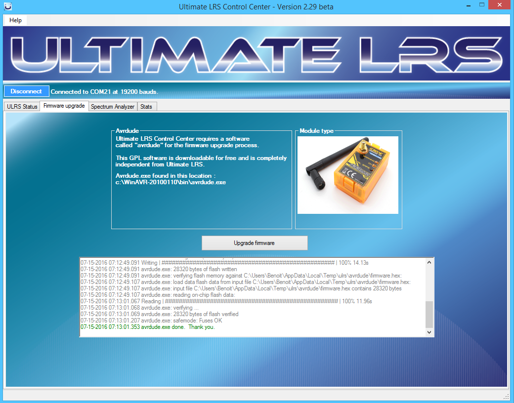
Firmware upgrade page
Well, it’s as simple as can be : After being connected, click on the Upgrade firmware button, and that’s it. And where do you select if it’s a TX or RX ? You don’t need to, because it’s the same firmware for TX and RX : if the firmware detects PPM it will act as a TX, else it will be a RX.
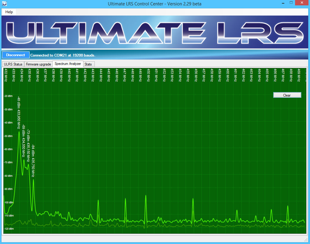
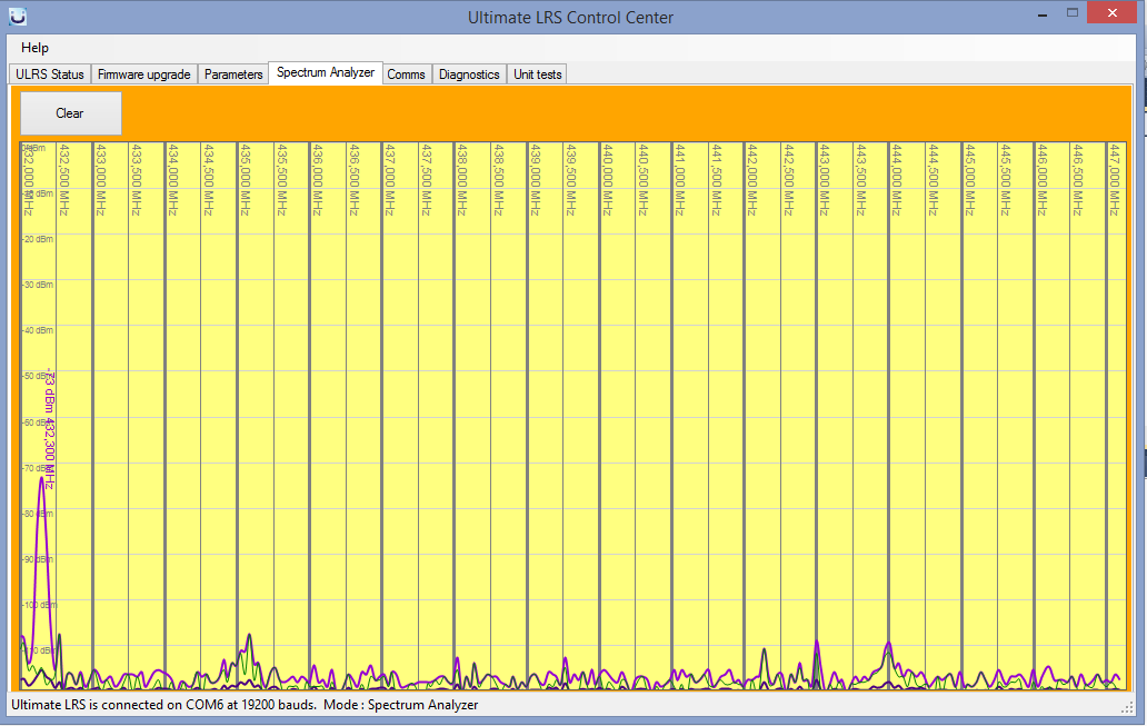
The Spectrum Analyzer page
This page shows a spectrum analyzer with the average and maximum values for all frequencies. Additional features are coming to select the start and stop frequencies, and be able to show the channels.
An interesting feature is that it provides a view over the full sensitivity of the RFM23BP, as shown below noise values down to -120 dBm are measured. The large peaks have their frequency and signal level displayed automatically:
Parameters
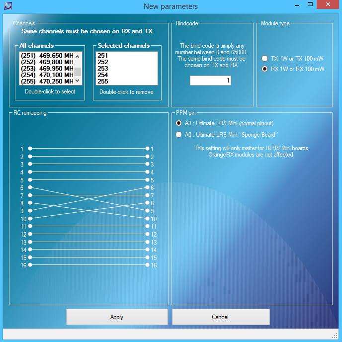
Click on the ‘Change parameters’ and you’ll get a popup showing the current parameters. The rule is very simple : select the same channels and bindcode on the TX and on the RX.
The bindcode can be seen as a simple signature. The TX and RX must have the same bindcode. ULRS will reject any packet that has not the bindcode it’s waiting for. This is important because the number of channels is not infinite, and it’s possible that someone picks one of the same channels you’ve selected.
Clicking on apply will save the parameters to the module.
The goal of this beta version is to test ULRS on different computers, identify bugs and collect your ideas and suggestions to improve the next release. You can bring any new idea or make comments on this page or by email.
Where do I start ?
Start by checking the material you’ll need.

Hi! Thanks a lot for yours work! Do you have a plan to make it work on other frequencies? I’ve build it for 433MHz-band but as I saw RFM23-modules are selling for working frequencies from 315MHz to 915MHz. With regards!
Hi Oleh, if there’s an upgrade it will be based on more recent RF chip, likely an RFM95PW or RFM96PW with lora and could consider to cover other frequency bands.
When I use the ULRS control center to connect to one of my Transmitters – the application won’t see the device unless it is also connected to a cPPM source. In other words I have to connect my radio to a joytstick or other cPPM source just to be able to connect to the app. Is this the correct behavior? I ask because I have several Transmitters and I want to set up the bind code and the FSK frequencies on my bench where I don’t typically have a cPPM generator. I spent quite a while going through every machination trying to connect to a transmitter before I figured out what the problem was.
Thank you
-Jim
You can use ULRS modules without a PPM source, however it’s possible that the connection to ULRS CC requires a PPM source to be present.
First let me say that I am a big fan of your work. I am not using ultimateLRS in an aircraft, but in a ground application where I need both cPPM and a serial link. I have a question about the serial link – I am sending 24byte packets periodically mostly for mode information. I stop sending the PPM signal and send a serial packet to the transmitter and then start up the PPM again. I have been doing it every 300ms and noticed that I am sometimes getting divided packets. It doesn’t seem like I need to interrupt my PPM stream to send the serial but I wanted to know how often do you send serial packets from the transmitter? There is no need for me to send more than the tx does and if I am in synch with the transmitted packets I won’t get divided packets on the receiver end.
Hi, it’s a good question, and the answer is it depends : the packets have a variable size, so rather than wait to fill a buffer before sending a packet, the TX will send a packet as soon as it has data to send. So if you’ve got small chunk of information to send, most of the time it will be splitted over at least two packets.
The reason is that else, after receiving 24 bytes we’d have to wait for an indetermined time to be sure there won’t be additional bytes that allow to fill our buffer.
So the choice was to send a packet as soon as some data is available, which reduces the overall delay (for data as well as for PPM).
In case there’s a higher rate of incoming data, the packets will get proressively larger until their maximum size which optimizes the throughput.
So this algorithm works very well in practice, and adapts continuously the packets size according to the data received. So for mavlink it’s perfect. In your case it’s not so bad, you receive quickly the data even if it’s splitted in two packets.
Thank you for the reply, and I’m sorry for the delay getting back to you – I lost the location of this post. So, if I have 24 contiguous bytes – you will send the 24 bytes you get as you get them. Do you wait for a break in the data to send or is it by the byte as you receive it. I ask because I have an Rx recovery routine that times out, so split packets are fine as long as I know what the space is between the parts. Does stopping my cPPM have any effect on the serial transmission? What do think my maximum packet sending rate would be? Could I send a packet every 50ms, or 20ms? Thank you again
I developped this system a long time ago, so if I remember well : there are two possible approaches :
– either send whatever is currently in the serial buffer
– or wait a little delay to be sure that no additional bytes will arrive in the next milliseconds
The first option tends to generate many short packets and this is inefficient (as every packet has some additional bytes such as CRC etc). So I implemented the second option, but I don’t remember the exact delay value.
In your case, if you send 24 bytes, it will then wait a certain delay before sending it. If this is a problem you can also add some ‘random’ bytes after your 24 ‘real’ bytes, just to reach the size of a full packet, in this case it will be transmitted immediately.
Anyone with experience from using ULRS in multipoint setup? Is this possible?
Hello, it’s always point to point, like a normal RC transmitter.
Does it support PPM protocol without soldering nothing or converter PMW / PPM if I use only 8 channels ?
I would like to connect my FC to my Orange RX with one wire ?
(Instead of each wire for each channel)
Thanks
Yes it supports serial PPM protocol, so all channels go through a single wire : http://www.itluxembourg.lu/site/ultimate-lrs-wiring-diagram/
Your LRS datalink firmware is AWESOME! I’m a medium level FPV flier and I love radio theory, so I always wanted a telemetry. Your solution is truly Ultimate, as I only had to flash hardware that I have already been using, link is WAY better than 3DR radios, and it cost me just 10$ for a BlueTooth module.
I encountered only single systematic problem (ULRS CC freezes when BT virtual serial port is installed), and one weird problem which turned out to be a faulty piece of HW (doesn’t work as a RX, but strangely it work without problem as a TX). Still I was able to solve and set up everything in just 2 evenings.
I Ultimately thank you, developers, for your ultimate work on this truly Ultimate LRS 😀
Thanks for your comment, very happy to see that you got it working and that you enjoy it !
Hi this FW can be installed on WolfBox 433mhz ??
Hi, yes it supports Wolfbox 433MHz, you can find the list of supported hardware here : http://www.itluxembourg.lu/site/material/
I don’t know why, the software can flash the firmware but can’t change the parameters. (not driver’s problem)
Please ask your question in the rcgroups ULRS thread : https://www.rcgroups.com/forums/showthread.php?2037442-Ultimate-LRS-Hassle-Free-Full-Mavlink-16-Channels-Fly-More